
Lock nuts are available in numerous styles, grades, and finishes. The term “lock nut” is not meant to imply that there is an indefinite permanency of fixity once used. Most locknuts can be removed and some can even be reused if removed correctly. Lock nuts are most commonly available in ASTM A563 Grades A and DH and ASTM A194 Grade 2H. They are manufactured with a standard hex or a heavy hex pattern. Two of the most common lock nut styles are Anco and Tri-Lok. The Anco style is a self-locking nut with a ratchet pin that is made from stainless steel. This ratchet pin slides along the threads as the nut is spun onto the bolt and prevents the nut from backing off. One benefit to using an Anco style lock nut is that the ratchet pin can be bent back so that the nut can be easily removed if needed. The Tri-Lok style is a “prevailing-torque” locknut which is frictionally resistant to rotation due to the thread distortion on the top thread of the nut. For various other types of lock nuts, please call one of our estimators!
Since hot-dip galvanizing typically adds 2.2 to 5 mils of thickness to the threaded portion of a fastener, galvanized lock nuts are tapped oversized to compensate for the corrosion resistant coating on the bolts.
Finished Hex Dimensions
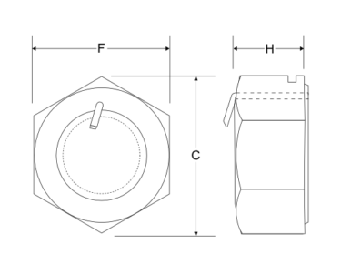
| Nominal Size | F | C | H | Weight Each (lbs.) | |||||
|---|---|---|---|---|---|---|---|---|---|
| Width Across Flats | Width Across Corners | Thickness | |||||||
| Basic | Max | Min | Max | Min | Basic | Max | Min | ||
| 1⁄2 | 3⁄4 | 0.750 | 0.736 | 0.866 | 0.840 | 7⁄16 | 0.448 | 0.427 | 0.04 |
| 5⁄8 | 15⁄16 | 0.938 | 0.922 | 1.083 | 1.051 | 35⁄64 | 0.559 | 0.535 | 0.07 |
| 3⁄4 | 11⁄8 | 1.125 | 1.088 | 1.299 | 1.240 | 41⁄64 | 0.665 | 0.617 | 0.12 |
| 7⁄8 | 15⁄16 | 1.312 | 1.269 | 1.516 | 1.447 | 3⁄4 | 0.776 | 0.724 | 0.19 |
| 1 | 11⁄2 | 1.500 | 1.450 | 1.732 | 1.653 | 55⁄64 | 0.887 | 0.831 | 0.28 |
| 11⁄8 | 111⁄16 | 1.688 | 1.631 | 1.949 | 1.859 | 31⁄32 | 0.999 | 0.939 | 0.40 |
| 11⁄4 | 17⁄8 | 1.875 | 1.812 | 2.165 | 2.066 | 11⁄16 | 1.094 | 1.030 | 0.54 |
| 13⁄8 | 21⁄16 | 2.062 | 1.994 | 2.382 | 2.273 | 111⁄64 | 1.206 | 1.138 | 0.73 |
| 11⁄2 | 21⁄4 | 2.250 | 2.175 | 2.598 | 2.480 | 19⁄32 | 1.317 | 1.245 | 0.94 |
| Dimensions per ASME B18.2.2 1987 (1999) | |||||||||
Heavy Hex Dimensions
| Nominal Size | F | C | H | Weight Each (lbs.) | |||||
|---|---|---|---|---|---|---|---|---|---|
| Width Across Flats | Width Across Corners | Thickness | |||||||
| Basic | Max | Min | Max | Min | Basic | Max | Min | ||
| 1⁄2 | 7⁄8 | 0.875 | 0.850 | 1.010 | 0.969 | 31⁄64 | 0.504 | 0.464 | 0.07 |
| 5⁄8 | 11⁄16 | 1.062 | 1.031 | 1.227 | 1.175 | 39⁄64 | 0.631 | 0.587 | 0.12 |
| 3⁄4 | 11⁄4 | 1.250 | 1.212 | 1.443 | 1.382 | 47⁄64 | 0.758 | 0.710 | 0.20 |
| 7⁄8 | 17⁄16 | 1.438 | 1.394 | 1.660 | 1.589 | 55⁄64 | 0.885 | 0.833 | 0.30 |
| 1 | 15⁄8 | 1.625 | 1.575 | 1.876 | 1.796 | 63⁄64 | 1.012 | 0.956 | 0.43 |
| 11⁄8 | 113⁄16 | 1.812 | 1.756 | 2.093 | 2.002 | 17⁄64 | 1.139 | 1.079 | 0.59 |
| 11⁄4 | 2 | 2.000 | 1.938 | 2.309 | 2.209 | 17⁄32 | 1.251 | 1.187 | 0.79 |
| 13⁄8 | 23⁄16 | 2.188 | 2.119 | 2.526 | 2.416 | 111⁄32 | 1.378 | 1.310 | 1.02 |
| 11⁄2 | 23⁄8 | 2.375 | 2.300 | 2.742 | 2.622 | 115⁄32 | 1.505 | 1.433 | 1.31 |
| 15⁄8 | 29⁄16 | 2.562 | 2.481 | 2.959 | 2.828 | 119⁄32 | 1.632 | 1.556 | 1.62 |
| 13⁄4 | 23⁄4 | 2.750 | 2.662 | 3.175 | 3.035 | 123⁄32 | 1.759 | 1.679 | 2.04 |
| 17⁄8 | 215⁄16 | 2.938 | 2.844 | 3.392 | 3.242 | 127⁄32 | 1.886 | 1.802 | 2.41 |
| 2 | 31⁄8 | 3.125 | 3.025 | 3.608 | 3.449 | 131⁄32 | 2.013 | 1.925 | 2.99 |
| 21⁄4 | 31⁄2 | 3.500 | 3.388 | 4.041 | 3.862 | 213⁄64 | 2.251 | 2.155 | 4.19 |
| 21⁄2 | 37⁄8 | 3.875 | 3.750 | 4.474 | 4.275 | 229⁄64 | 2.505 | 2.401 | 5.64 |
| 23⁄4 | 41⁄4 | 4.250 | 4.112 | 4.907 | 4.688 | 245⁄64 | 2.759 | 2.647 | 7.38 |
| 3 | 45⁄8 | 4.625 | 4.475 | 5.340 | 5.102 | 261⁄64 | 3.013 | 2.893 | 9.50 |
| 31⁄4 | 5 | 5.000 | 4.838 | 5.774 | 5.515 | 33⁄16 | 3.252 | 3.124 | 11.94 |
| 31⁄2 | 53⁄8 | 5.375 | 5.200 | 6.207 | 5.928 | 37⁄16 | 3.506 | 3.370 | 15.26 |
| 33⁄4 | 53⁄4 | 5.750 | 5.562 | 6.640 | 6.341 | 311⁄16 | 3.760 | 3.616 | 18.12 |
| 4 | 61⁄8 | 6.125 | 5.925 | 7.073 | 6.755 | 315⁄16 | 4.014 | 3.862 | 21.80 |
| Dimensions per ASME B18.2.2 1987 (1999) | |||||||||