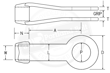
Portland Bolt Expands with Acquisition of Bennett Bolt Works
Press Release
Portland Bolt & Manufacturing Company
Email Us Get a Quote (800) 547-6758
Skip to content
  • Home
  • Products
    • Headed Bolts
      • Hex Bolts
      • Heavy Hex Bolts
      • Structural Bolts
      • Square Head Bolts
      • Timber Bolts
      • Headed Anchor Bolts
      • Hex Lag Screw
      • Square Lag Screws
      • Carriage Bolts
      • Timber Spikes
      • Machine Bolts
      • Washer Head Bolts
      • Round Head Bolts
      • Countersunk Bolts
      • Step Bolts
      • Custom Heading
    • Rods
      • Anchor Rods
      • All Thread Rods
      • Tie Rods
      • Drift Pins
      • Swedged Rods
      • Threaded Rebar
    • Bent Bolts
      • 90° Anchor Bolt
      • Round U-Bolts
      • Square U-Bolts
      • Closed Eye Bolt
      • Open Eye Bolt
      • Round Hook
      • Square Hook
      • J-Bolts
      • Custom Bent
    • Anchor Bolts and Anchor Rods
      • 90° Anchor Bolt
      • Headed Anchor Bolts
      • Anchor Rods
      • All Thread Rods
      • Swedged Rods
    • Nuts
      • Hex Nuts
      • Heavy Hex Nuts
      • Square Nuts
      • Hex Jam Nuts
      • Heavy Jam Nuts
      • Lock Nuts
      • Hex Coupling Nuts
      • Sleeve Nuts
    • Washers
      • Standard Washers
      • F436 Hardened Washers
      • Lock Washers
      • Malleable Iron Washers
      • Round Plate Washers
      • Square Plate Washers
      • Ogee Washers
      • Beveled Washers
      • Hardened Beveled Washers
      • Clipped Hardened Washers
      • Load Indicating Washers (DTI)
      • Rosette Washers
      • Hillside Washers
    • Other
      • Barrier Pins
      • Plates
      • Turnbuckles
      • Clevises
      • Anchor Sleeves
      • Shear Plates
      • Dapping Tools
      • Split Rings
      • Grooving Tools
      • Boat Spikes
      • Spike Grids
    • Product Line Card
  • Manufacturing
    • CNC Lathe
    • Hot-Dip Galvanizing
    • Heading
    • Threading
    • Cutting
    • Plate Fabrication
    • Bending
    • Miscellaneous Capabilities
    • Shipping
    • Certification & Testing
    • Steel
  • Industries
    • Marine Construction
    • Steel Fabrication
    • Highway Construction
    • Timber Construction
    • Power and Energy
    • Precast Concrete
    • Light Pole and Traffic Signal
    • Pole Line Hardware
    • Light Rail
    • Mining
    • OEM
    • Engineers and Architects
    • Government and Military
  • Technical Tools and Information
    • FAQs
      • Newest FAQs
      • The Experts
      • FAQ Categories
      • Ask a Question
    • Calculators & Tools
      • Bolt Weight Calculator
      • Tie Rod Calculator
      • Plate Weight Calculator
      • Bolt Torque Calculator
    • Specifications
      • AASHTO
      • ASTM
      • SAE
      • CSA
    • Fastener Identification Markings
    • Strength Requirements by Grade
    • Nut Compatibility Chart
    • Thread Pitch Chart
    • Steel Hardness Conversion
    • Lag Screw Pilot Hole Diameters
    • AASHTO to ASTM Conversions
    • Structural Bolt Weight Chart
    • Nut Weight Chart
    • Bolt Torque Chart
    • Bolt Glossary
  • FAQs
    • Newest FAQs
    • The Experts
    • FAQ Categories
    • Ask a Question
  • About Us
    • Projects
      • Power & Energy
      • Industrial
      • Marine
      • Bridges
      • Covered Bridges
      • Light Rail
      • Government & Military
      • Amusement Parks
      • Stadiums
      • International
      • Miscellaneous
      • Videos
    • Recent Shipment Destinations
    • Testimonials
    • News
    • Newsletter
    • Credit Application
    • Careers
    • Leave Feedback
    • Fun Zone
    • Contact Us
    • Meet the Team
    • History
    • Videos
    • Live Video Feeds

Clevis Dimensions

Click table to show drawing
Clevis Number Dimensions in Inches Weight
w/ Pin,
lbs.
Available Strength, kips Grip Part Numbers
Max, W Max, P D N A L T ASD LRFD Min Max Plain Galvanized
2 5/8 3/4 17/16 5/8 39/16 11/16 5/16 (+1/32 , -0) 1.5 5.83 8.75 3⁄4 3⁄4 17150 17151
21/2 7/8 11/2 21/2 1 4 11/4 5/16 (+1/32 , -0) 2.5 12.5 18.8 3⁄4 11⁄4 17152 17153
3 13/8 13/4 3 11/4 51/16 11/2 1/2 (+1/16 , -1/32) 5.0 25 37.5 3⁄4 11⁄2 17154 17155
31/2 11/2 2 31/2 11/2 6 13/4 1/2 (+1/16 , -1/16) 8.0 30 45 3⁄4 2 17156 17157
4 13/4 21/4 4 13/4 515/16 2 1/2 (+1/16 , -1/16) 11.0 35 52.5 3⁄4 21⁄4 17158 17159
5 2 21/2 5 21/4 7 21/2 5/8 (+3/32 , -0) 21.0 62.5 93.8 3⁄4 2-3⁄4 17160 17161
6 21/2 3 6 23/4 8 3 3/4 (+3/32 , -0) 32.0 90 135 1 31⁄2 17162 17163
7 3 33/4 7 3 9 31/2 7/8 (+1/8 , -1/16) 53.0 114 171 1 41⁄2 17164 17165
8 4 41/4 8 4 101/8 4 11/2 (+1/8 , -1/16) 80.0 225 338 1 5 17166 17167

Dimensions per AISC Steel Construction Manual fourteenth edition page 15-14 ASD - Allowable Stress Design LRFD - Load and Resistance Factor Design

Note: The grip size is normally specified as material thickness +¼", within the constraints of the above table.

Close Window Print this page
© 1996-2025 Portland Bolt & Manufacturing Company | (800) 547-6758 | www.portlandbolt.com