

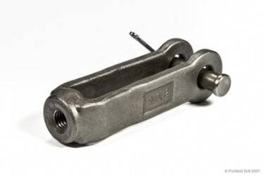

Clevises are provided as components of tie rod assemblies that Portland Bolt manufactures and are often used in conjunction with turnbuckles. In a typical cross bracing assembly, a threaded rod is supported at each end by a clevis. One end of each clevis will grip onto a steel plate and is secured with a pin.
When a single tie rod is used between two clevises, one end of the assembly uses right-hand thread and the other end uses left-hand thread. As the rod is turned, the assembly draws tight. When a turnbuckle dissects the rod assembly, both clevises (and the end of the rods threading into them) will use right-hand thread. The opposite end of one of the two rods which make up the assembly will require left-hand thread to mate with the turnbuckle.
When ordering clevises, there are several pieces of information that need to be specified including clevis number, finish, diameter of tap, thread direction, grip, and pin.
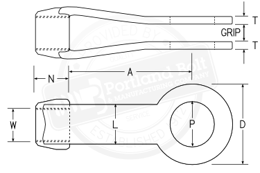
- Clevis Number: The clevis number will identify the physical size of the forging. The clevis number corresponds to the “D” dimension on the drawing above. Only certain diameters of rods and pins will function properly with specific clevis numbers, so refer to the charts below for acceptable combinations.
- Finish: Plain or hot-dip galvanized. Galvanized clevises will be tapped oversize to accept the threads of a hot-dip galvanized rod.
- Diameter of Tap: The tap is the internally threaded “nut” portion of the clevis (dimension “W” above). The threaded rod will engage into the tap. The tap diameter will need to be specified when ordering. It is advisable to specify an “oversize” tap when ordering galvanized clevises, as the internal threads will be enlarged to accommodate the galvanized rod.
- Thread Direction: When a single rod is connected with a clevis on each end, typically one clevis will possess right-hand thread, while the other clevis will possess left-hand thread. Therefore, half of the clevises will be left hand, while the other half will be right hand. If a turnbuckle lies in the middle of an assembly, both clevises typically possess right-hand threads.
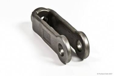
- Grip: The grip of a clevis is the portion that slides over the gusset plate and is secured with a pin. Typically, the grip is ¼” larger than the thickness of the gusset plate.
- Pin: The diameter and type of pin should be specified when ordering. The standard clevis pin is a piece of round bar with drilled holes and cotters on each end. This pin would be supplied if no type is specified. The pin slides through the gusset plate and clevis, is secured with the cotters, and attaches the tie rod assembly to the gusset plate. Headed pins are also available, and engineers sometimes even specify A325 heavy hex structural bolts to be used as clevis pins. The length of the clevis pin will be determined by the clevis number and grip dimension and typically does not need to be specified when ordering.
A typical order would look like this:
Quantity of 32 pieces – #3 galvanized clevis with 1” right hand (oversize) tap, 1” grip, and 3/4” pin.
Our tie rod calculator will quickly determine rod lengths when given overall pin-to-pin dimensions of a tie rod assembly.
Availability
Clevises are not a stocked item but are available within a day or two. Clevises are provided in both plain finished and hot-dip galvanized medium carbon steel as well as stainless steel. Custom and nonstandard clevises are also available.
Dimensions
| Clevis Number | Dimensions in Inches | Weight w/ Pin, lbs. | Available Strength, kips | Grip | Part Numbers | |||||||||
|---|---|---|---|---|---|---|---|---|---|---|---|---|---|---|
| Max, W | Max, P | D | N | A | L | T | ASD | LRFD | Min | Max | Plain | Galvanized | ||
| 2 | 5/8 | 3/4 | 17/16 | 5/8 | 39/16 | 11/16 | 5/16 (+1/32 , -0) | 1.5 | 5.83 | 8.75 | 3⁄4 | 3⁄4 | 17150 | 17151 |
| 21/2 | 7/8 | 11/2 | 21/2 | 1 | 4 | 11/4 | 5/16 (+1/32 , -0) | 2.5 | 12.5 | 18.8 | 3⁄4 | 11⁄4 | 17152 | 17153 |
| 3 | 13/8 | 13/4 | 3 | 11/4 | 51/16 | 11/2 | 1/2 (+1/16 , -1/32) | 5.0 | 25 | 37.5 | 3⁄4 | 11⁄2 | 17154 | 17155 |
| 31/2 | 11/2 | 2 | 31/2 | 11/2 | 6 | 13/4 | 1/2 (+1/16 , -1/16) | 8.0 | 30 | 45 | 3⁄4 | 2 | 17156 | 17157 |
| 4 | 13/4 | 21/4 | 4 | 13/4 | 515/16 | 2 | 1/2 (+1/16 , -1/16) | 11.0 | 35 | 52.5 | 3⁄4 | 21⁄4 | 17158 | 17159 |
| 5 | 2 | 21/2 | 5 | 21/4 | 7 | 21/2 | 5/8 (+3/32 , -0) | 21.0 | 62.5 | 93.8 | 3⁄4 | 2-3⁄4 | 17160 | 17161 |
| 6 | 21/2 | 3 | 6 | 23/4 | 8 | 3 | 3/4 (+3/32 , -0) | 32.0 | 90 | 135 | 1 | 31⁄2 | 17162 | 17163 |
| 7 | 3 | 33/4 | 7 | 3 | 9 | 31/2 | 7/8 (+1/8 , -1/16) | 53.0 | 114 | 171 | 1 | 41⁄2 | 17164 | 17165 |
| 8 | 4 | 41/4 | 8 | 4 | 101/8 | 4 | 11/2 (+1/8 , -1/16) | 80.0 | 225 | 338 | 1 | 5 | 17166 | 17167 |
Dimensions per AISC Steel Construction Manual fourteenth edition page 15-14 ASD - Allowable Stress Design LRFD - Load and Resistance Factor Design Note: The grip size is normally specified as material thickness +¼", within the constraints of the above table. | ||||||||||||||
Clevis Numbers for Various Rods and Pins
| Dia. of Tap, in. | Diameter of Pin in Inches | |||||||||||||||||
|---|---|---|---|---|---|---|---|---|---|---|---|---|---|---|---|---|---|---|
| 1/2 | 5/8 | 3/4 | 7/8 | 1 | 11/4 | 11/2 | 13/4 | 2 | 21/4 | 21/2 | 23/4 | 3 | 31/4 | 31/2 | 33/4 | 4 | 41⁄4 | |
| 1/2 | 2 | 2 | 2 | |||||||||||||||
| 5/8 | 2 | 2 | 2 | 21/2 | 21/2 | 21/2 | 21/2 | |||||||||||
| 3/4 | 21/2 | 21/2 | 21/2 | 21/2 | 21/2 | |||||||||||||
| 7/8 | 21/2 | 21/2 | 21/2 | 21/2 | 3 | |||||||||||||
| 1 | 3 | 3 | 3 | 3 | ||||||||||||||
| 11/8 | 3 | 3 | 3 | 3 | 31/2 | |||||||||||||
| 11/4 | 3 | 3 | 3 | 3 | 31/2 | |||||||||||||
| 13/8 | 3 | 3 | 3 | 31/2 | 31/2 | 4 | ||||||||||||
| 11/2 | 31/2 | 31/2 | 4 | 4 | 5 | |||||||||||||
| 15/8 | 4 | 4 | 4 | 5 | 5 | 5 | ||||||||||||
| 13/4 | 4 | 5 | 5 | 5 | 5 | |||||||||||||
| 17/8 | 5 | 5 | 5 | 5 | 5 | |||||||||||||
| 2 | 5 | 5 | 5 | 5 | 5 | 6 | 6 | |||||||||||
| 21/4 | 6 | 6 | 6 | 6 | 6 | 7 | 7 | |||||||||||
| 21/2 | 6 | 6 | 6 | 7 | 7 | 7 | 7 | 7 | ||||||||||
| 2 3/4 | 7 | 7 | 7 | 7 | 8 | 8 | ||||||||||||
| 3 | 7 | 8 | 8 | 8 | 8 | 8 | 8 | 8 | ||||||||||
| 31/4 | 8 | 8 | 8 | 8 | 8 | 8 | 8 | |||||||||||
| 31/2 | 8 | 8 | 8 | 8 | 8 | 8 | ||||||||||||
| 33/4 | 8 | 8 | 8 | 8 | 8 | |||||||||||||
| 4 | 8 | 8 | ||||||||||||||||
Dimensions per AISC Manual of Steel Construction thirteenth edition page 15-15 | ||||||||||||||||||