

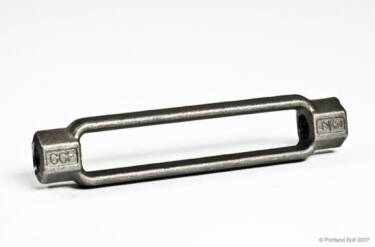
Turnbuckles are provided as components of tie rod assemblies that Portland Bolt manufactures and are often used in conjunction with clevises. Turnbuckles possess right hand internal threads on one end and left hand internal threads on the other. By rotating the turnbuckle, the tie rod assembly is drawn tight.
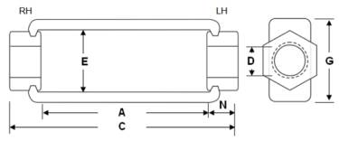
Turnbuckles are measured by the length of the take-up as opposed to overall length. Therefore, a 2″ x 6″ turnbuckle refers to a turnbuckle with a 6″ window (“A” dimension in the line drawing on this page). Turnbuckles are typically not specified by their overall length, which in this example is 11-5/8″.
Our new tie rod calculator will quickly determine rod lengths when given overall pin-to-pin dimensions of a tie rod assembly.
Availability
Turnbuckles are stocked in limited sizes, and most sizes that are not in stock are available within a day or two. Turnbuckles are provided in both plain finished and hot-dip galvanized medium carbon steel as well as stainless steel.
Dimensions
| Dia. (D), in. | Standard Turnbuckles | Weight in Pounds | Safe Working Load, Kips | Part Numbers (6 inch) | |||||||||||
|---|---|---|---|---|---|---|---|---|---|---|---|---|---|---|---|
| Dimensions, Inches | Length, Inches | ||||||||||||||
| A | N | C | E | G | 6 | 9 | 12 | 18 | 24 | 36 | ASD | LRFD | Plain | Galvanized | |
| 1⁄2 | 6 | 25⁄32 | 79⁄16 | 11⁄16 | 15⁄16 | .65 | .90 | 1.20 | 3.67 | 5.50 | 18707 | 18719 | |||
| 5⁄8 | 6 | 15⁄16 | 77⁄8 | 13⁄16 | 11⁄2 | .98 | 1.35 | 1.58 | 2.43 | 5.83 | 8.75 | 18708 | 18720 | ||
| 3⁄4 | 6 | 11⁄16 | 81⁄8 | 15⁄16 | 123⁄32 | 1.45 | 1.84 | 2.35 | 3.06 | 8.67 | 13.0 | 18709 | 18722 | ||
| 7⁄8 | 6 | 15⁄16 | 85⁄8 | 13⁄32 | 17⁄8 | 1.85 | 3.02 | 4.20 | 12.0 | 18.0 | 18710 | 18723 | |||
| 1 | 6 | 17⁄16 | 87⁄8 | 19⁄32 | 21⁄32 | 2.60 | 4.02 | 4.40 | 6.85 | 10.0 | 15.5 | 23.3 | 18711 | 18724 | |
| 11⁄8 | 6 | 19⁄16 | 91⁄8 | 113⁄32 | 29⁄32 | 4.06 | 4.70 | 6.10 | 19.3 | 29.0 | 18712 | 18725 | |||
| 11⁄4 | 6 | 19⁄16 | 91⁄8 | 19⁄16 | 217⁄32 | 4.00 | 6.49 | 7.13 | 11.30 | 13.1 | 25.3 | 38.0 | 18713 | 18726 | |
| 13⁄8 | 6 | 113⁄16 | 95⁄8 | 111⁄16 | 23⁄4 | 6.15 | 29.0 | 43.5 | 18714 | 18727 | |||||
| 11⁄2 | 6 | 17⁄8 | 93⁄4 | 127⁄32 | 31⁄32 | 6.15 | 9.70 | 9.13 | 16.80 | 19.4 | 35.0 | 52.5 | 18715 | 18728 | |
| 15⁄8 | 6 | 21⁄2 | 11 | 131⁄32 | 3⁄32 | 9.80 | 40.9 | 61.3 | - | - | |||||
| 13⁄4 | 6 | 21⁄2 | 11 | 21⁄8 | 39⁄16 | 9.80 | 15.3 | 16.0 | 19.5 | 47.2 | 70.8 | 18716 | 18729 | ||
| 17⁄8 | 6 | 213⁄16 | 115⁄8 | 23⁄8 | 4 | 14.0 | 15.3 | 62.0 | 93.0 | - | - | ||||
| 2 | 6 | 213⁄16 | 115⁄8 | 23⁄8 | 4 | 14.0 | 15.3 | 27.5 | 62.0 | 93.0 | 18717 | 18730 | |||
| 21⁄4 | 6 | 35⁄16 | 125⁄8 | 211⁄16 | 45⁄8 | 19.6 | 30.9 | 43.5 | 80.0 | 120 | - | - | |||
| 21⁄2 | 6 | 33⁄4 | 131⁄2 | 3 | 5 | 23.3 | 30.9 | 42.4 | 100 | 150 | - | - | |||
| 23⁄4 | 6 | 43⁄16 | 143⁄8 | 31⁄4 | 55⁄8 | 31.5 | 54.0 | 125 | 188 | - | - | ||||
| 3 | 6 | 45⁄16 | 145⁄8 | 35⁄8 | 61⁄8 | 39.5 | 161 | 242 | - | - | |||||
| 31⁄4 | 6 | 57⁄16 | 167⁄8 | 37⁄8 | 63⁄4 | 60.5 | 79.5 | 203 | 305 | - | - | ||||
| 31⁄2 | 6 | 57⁄16 | 167⁄8 | 37⁄8 | 63⁄4 | 60.5 | 70.0 | 79.5 | 203 | 305 | - | - | |||
| 33⁄4 | 6 | 6 | 18 | 45⁄8 | 81⁄2 | 95.0 | 280 | 420 | - | - | |||||
| 4 | 6 | 6 | 18 | 45⁄8 | 81⁄2 | 95.0 | 280 | 420 | - | - | |||||
| 41⁄4 | 9 | 63⁄4 | 221⁄2 | 51⁄4 | 93⁄4 | 152 | 390 | 585 | - | - | |||||
| 41⁄2 | 9 | 63⁄4 | 221⁄2 | 51⁄4 | 93⁄4 | 152 | 390 | 585 | - | - | |||||
| 43⁄4 | 9 | 63⁄4 | 221⁄2 | 51⁄4 | 93⁄4 | 152 | 390 | 585 | - | - | |||||
| 5 | 9 | 71⁄2 | 24 | 6 | 10 | 200 | 491 | 737 | - | - | |||||
Dimensions per AISC Manual of Steel Construction thirteenth edition page 15-16 ASD - Allowable Stress Design (according to the AISC 9th Ed.) LRFD - Load and Resistance Factor Design (according to AISC 3rd Ed.) | |||||||||||||||